How To Create Gcode From Stl
When you're starting out with CNC or 3D Printing, the first thing you'll want to get your arms around is creating some sort of model, drawing, or representation of your part. Most of the time this is a function of a CAD program, but not always. You may also need to start from images, vector art from a drawing program, or perhaps some other file types. You might even want to start with a list of simple machining operations, much the way you'd approach creating a part "off the cuff" and without drawings on a manual machine tool.
The very next thing you will need to do is convert whatever representation of your part that you have into GCode, because that's what CNC Machines run. Let's go through some of these different paths to give you a good idea of what kind of software you'll want to have around to get the job of generating GCode done.
3D Printing and Slicers
3D Printers typically use software that "slices" a 3D model of a part into layers, and then they generate g-code that extrudes plastic to fill each layer. There are a number of different software packages out that can serve as your Slicer, and most 3D Printers come with one program or another. Some amount of hand tweaking of the parameters is needed for best results, but in many cases, Slicers are simpler software than the software used to generate GCodes for subtractive machining such as you'd need for a milling machine, CNC router, or lathe.
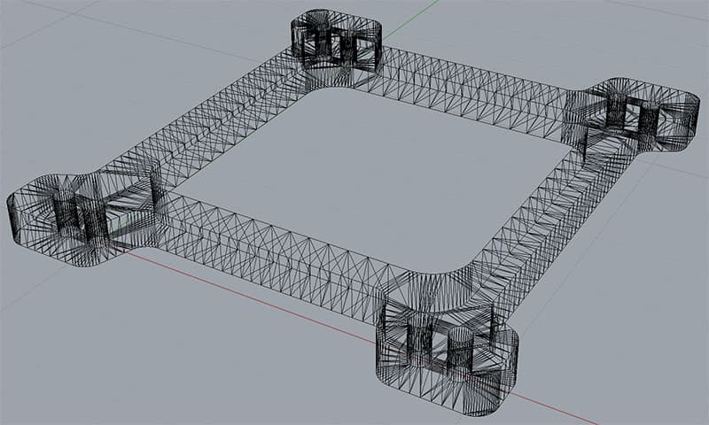
Most Slicer software works from an STL (Stereo Lithography) file, so make sure you're using a CAD program that can generate STL's. Most CAD that's 3D capable will do so, as STL is sort of the lowest common denominator file format. STL files consist of many linked triangles (called a "mesh") that simulate the surface of the object you want to print.

STL mesh model of a carburetor spacer…
DXF and 2D CAD Formats to GCode
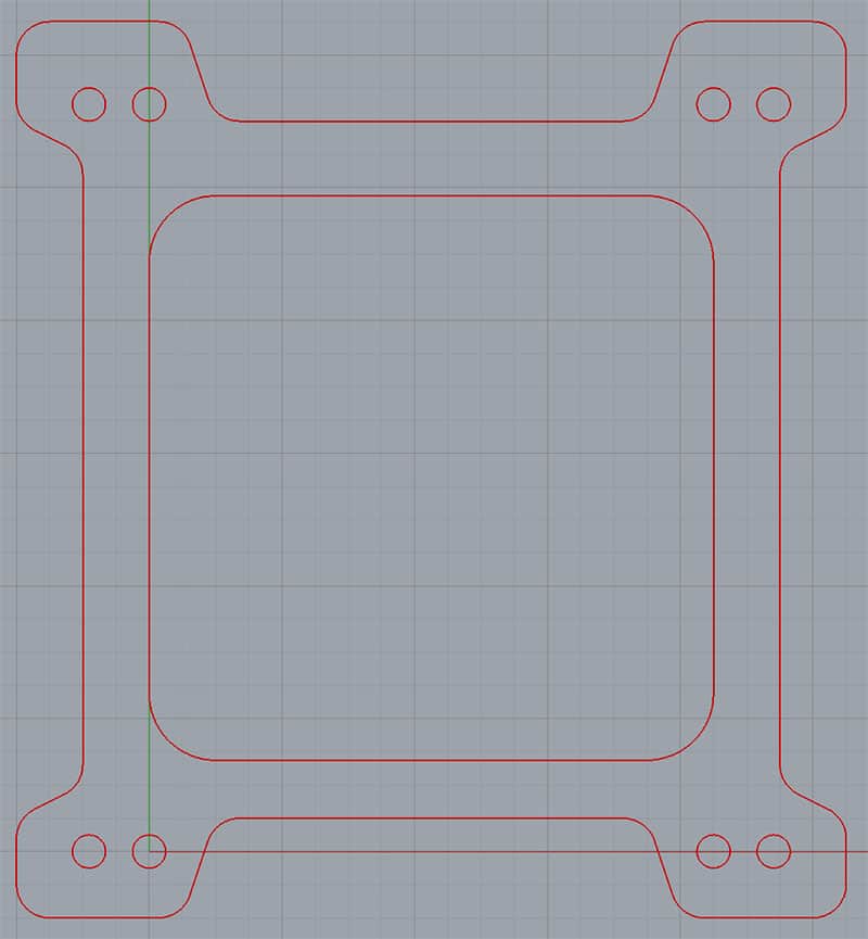
While STL files are the most common 3D file format, there are 2D CAD files as well. These are not so useful for making 3D parts, but they are still very popular for CNC work because a lot that goes on can be represented in 2D. Take our Carb Spacer STL shown above. The part is flat on the top and the bottom. There really are no interesting 3D features, it is the outline that makes the part and the outline is 2D. The most common file format for 2D work is Autodesk's ubiquitous DXF format. Here is a DXF outline of the same part:

A DXF model of a part is a 2D model…
Unless you're planning to exclusively focus on 3D Printing, I recommend you make sure you CAD software can handle DXF files as they come up an awful lot for CNC work.
Tip: Check our library for free DXF files that you can use in your designs.
How do we convert a DXF to GCode?
That depends on how you want to go about it. In all likelihood you'll want to use a CAM package to generate the g-code from your DXF. The process is pretty straightforward as this video showing that part being made with Cambam shows:
[youtube]http://www.youtube.com/watch?v=2dQkNpM3GtY[/youtube]
In general, you're selecting the various outlines, telling the CAM package what kind of feature they represent (pocket or profile), as well as what it needs to know about the feature (how deep is it, what feeds and speeds to use, how to enter and exit the cut, how many steps down to take, etc.).
A lot of that information has to do with the fact that even though the model is 2D, a 3D part must be made. When there's only a 2D file available, the CAM software looks to the user to fill in the 3D blanks. For simple parts, this is not too hard. But for more complex parts, it is often easier to keep track of what's going on and simpler to tell the CAM software what it needs to know if you have a 3D model. The good news is that it is possible to convert a 2D CAD file such as a DXF to a 3D Model pretty easily in most CAD packages.
Let's say you're given a DXF that you want to convert to a 3D model. Maybe you got that carb spacer drawing right off some carburetor manufacturer's web site, and you'd like to work from a 3D model, whether because you're going to use a 3D printer, or because it's just faster and easier to use 3D with your CAM. To do so, you'll need two things:
1. A 3D CAD package that can read DXF files
2. The ability in your 3D CAD package to extrude the outline to create a 3D model.
Extrusion is a pretty easy concept to grasp. Imagine you're going to copy the outline and shift it in the Z dimension by some amount. Further, assume the space between the two is filled with solid material. Now you have a 3D model of your object that you can export to whatever file format your CAM software or 3D Printing Slicer can accept.
Note that if you don't have a full 3D CAD package, all may not be lost. Many CAM packages, such as MeshCam, can do the extrusion for you. Some even have fairly powerful CAD built in, although most of the time you're going to be better off with a purpose-built CAD package as the integrated CAM-CAD (that's a tongue twister) is often just not as good.
Converting 3D CAD Files to GCode
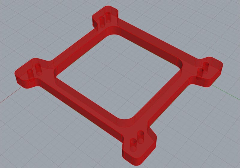
For most CNC work, this is what you'll want to be doing. While there's still a lot of 2D CAD work out there, 3D is taking over fast, especially for this kind of thing. Here's a typical 3D model of the same carb spacer:

3D Model of Carb Spacer…
It's starting to look a little more intuitive and requires less imagination than the STL Mesh or the DXF Outline. Going from a model like this to GCode requires 3D CAM software. The level of difficulty will be a function of which CAM software you choose.
For example, MeshCam, the 3D CAM package we offer to beginners, is especially designed to be as simple as possible. It may not always produce the absolute fastest most high performance GCode, but you're unlikely to find a package that can get you workable GCode as quickly and easily as MeshCam. If you want to get started making some parts quickly, I always tell beginners to start with MeshCam. In fact, it's so good that it's the heart of the software suite for the CNC-For-The-Rest-Of-Us Mill, the Nomad. It's inexpensive enough that you can buy it, make a bunch of parts and really learn all about CNC, and then if you discover you want something more powerful, you can pick up a more full-featured package later.
If you don't have a product like MeshCam, you'll need to learn a lot more about different toolpath types and how to use them to create whatever shape you want. Having a lot of different toolpaths available is a two-edged sword. On the one hand, it can help you pick out the path that is optimized for your job. If you're a commercial CNC'er, this will save you money that goes straight to the bottom line. On the other hand, it forces the beginner to learn a bewildering array of new terminology and techniques that they're probably not ready for yet.
Fortunately, most CAM software is available on a trial basis. Take advantage of it. Before you sign up for the trials, draw up some sample parts you'd like to make in your CAD software. If the CAD software is new too, then this is a good way to get more familiar with it. Try to create 3 or 4 different parts of various kinds, some 2 1/2D like our Carb Spacer (in other words, they could be largely specified as outlines) and some full 3D models.
Next, sign up for 2 or 3 different CAM package trials. Try out your models with the CAM software. See which package is most intuitive for you to learn. Get an idea of which package has sufficient YouTube videos and user forums to help you on your learning quest. Try to make an actual part on your CNC using GCode generated by each of the CAM packages you're evaluating. Once you've done that, you'll have a much better idea how to proceed.
Lastly, don't be afraid to start out planning to own more than one CAM package. Get something inexpensive and easy, like MeshCam, so you can make parts sooner. Plan to upgrade to a more full-featured package later, when the rest of your CNC skills are up to speed and you start feeling like your entry-level CAM package is holding you back. You may never quit using that super simple package though. I know of a number of machinists who keep two packages. They pull out the simple one for quick and dirty things like fixtures, and keep the fancy one for cases where there's real money riding on how fast the part can be made and maximum flexibility is the name of the game.
Converting Image and Vector Artwork to GCode
Are you an artist who is trying to convert your designs from concepts to reality? Maybe you want to engrave some fancy pattern, or perhaps you're just more comfortable sketching than mousing. Perhaps you're trying to work from a photo more than a precision dimensioned mechanical model. If any of these are true, you may want to be able to convert images into GCode rather than starting from CAD at all. CAD is great for parts that must have particular dimensions and particularly for parts that have lots of rectangles, round holes, and straight lines in them. But most CAD becomes painful in a hurry when smooth flowing shapes are called for (Rhino3D being one exception that comes to mind). There are three ways to approach this problem.
First, there are CAM packages that are adept at accepting images and converting them to models from which they can generate their GCode. MeshCam Pro is a good example of this. Here's a neat video of a brass bracelet being made using MeshCam Pro from a sketch:
[youtube width="800″ height="547″]http://www.youtube.com/watch?v=8HGy2u1uURU[/youtube]
GCode from a Sketch: No CAD Required!
Second, your CAD package may be able to accept image or vector artwork and convert it to a CAD model. This is often called "Tracing", and not all CAD packages can do it. Some will let you put the bitmap onto its own layer and they expect you to trace it manually. It's easier than it sounds, but definitely not as nice as automatic tracing.
Lastly, you may be able to use a drawing program of some kind to convert from a bitmap to a suitable CAD format. For example, Adobe Illustrator can output a DXF file format and it can automatically trace images. If you do a lot of this artistic work, it's not a bad idea to have a program like Illustrator in your toolbox.
Working Without Drawings for a Quick and Dirty Project, ala Manual Machining
A good manual machinist can accomplish a whole lot without stopping to create a CAD drawing of the part they're trying to make. They won't try this on a really complex part, and they may work from a quick back of the envelope sketch, but they can often avoid the overhead and time spent to create a CAD drawing to be productive. This is especially true for lathe work. Many times when the age old argument over whether manual machining can ever be faster than CNC breaks out, one of the major complaints about CNC is this idea that you must always start from a CAD drawing. The reality is that you can use a capability known as "Conversational CNC" to accomplish most anything in CNC that a manual machinist can do without recourse to CAD or CAM.
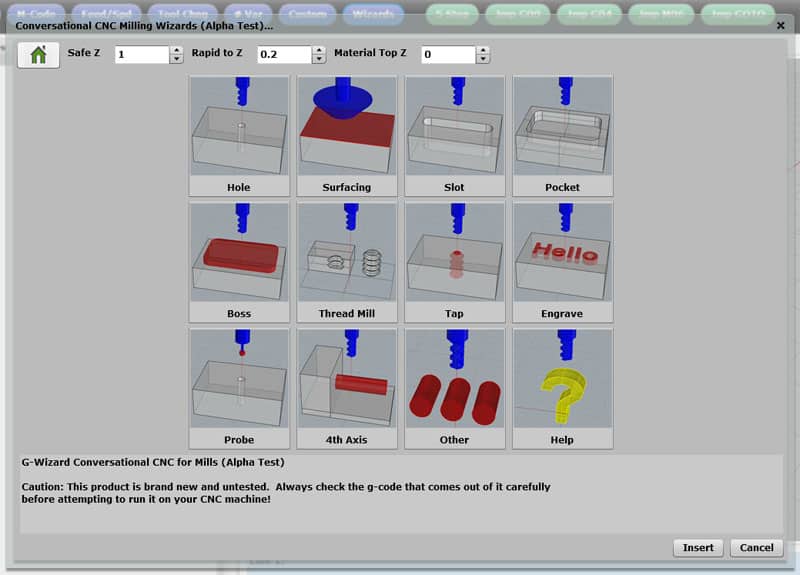
Conversational CNC is all about selecting a "Wizard" from a group of standard operations:

Conversational CNC starts with selecting from a menu of common operations…
We offer a Conversational CNC capability as an integrated part of our G-Wizard GCode Editor. It's easy to use and will get you into CNC fast if you're a manual machinist as well as saving you time for quick and dirty work of various kinds. You may even find that some of the capabilities like the fancy Facing or Deep Hole Drilling Wizards are better than what you CAM offers, and you want to substitute them in place of the equivalent CAM functions.
Conclusions
As we've seen, there are a variety of ways to go about generating GCode programs for your CNC Machine or 3D Printer. I've tried to help beginners understand the ins and outs of the various methods so you can get an idea where to start. GCode is a useful common denominator to be able to feed with so many different tools. Having these extra approaches in your hip pocket gives you that much more flexibility when a new and interesting job comes in over the transom and you're looking for a way to make it easier.
Join 100,000+ CNC'ers! Get our latest blog posts delivered straight to your email inbox once a week for free. Plus, we'll give you access to some great CNC reference materials including:
How To Create Gcode From Stl
Source: https://www.cnccookbook.com/secrets-going-cad-image-dxf-stl-gcode-cnc-3d-printing/
Posted by: mcgrathextured.blogspot.com

0 Response to "How To Create Gcode From Stl"
Post a Comment